Understanding the Framing Plan, Lumber Size, Spacing, Trusses, and Roof Framing
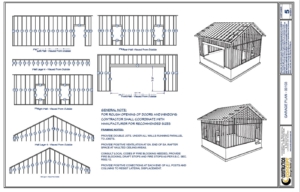
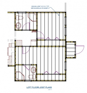
 A framing plan is an essential document in the construction of a building. It provides critical details about the structure’s skeleton, outlining how the building will be supported and how the components will fit together. This includes information on lumber sizes, spacing, trusses, and roof framing. Below is a breakdown of the primary elements you will typically find in a framing plan and what they signify.
1. Lumber Size and Specifications
One of the most important components of the framing plan is the specification of lumber sizes. Lumber, used for structural framing, comes in various sizes depending on the type of load it will support and its location within the building. The framing plan will indicate the dimensions (height, width, and length) of the various framing members, such as studs, joists, beams, and headers.
For example, you might see:
- Wall Studs: Typically, studs in load-bearing walls are 2×4 or 2×6 pieces of lumber spaced at regular intervals, often 16 or 24 inches apart.
- Floor Joists: Common sizes for floor joists are 2×8, 2×10, or 2×12, depending on the load they must bear and the span they need to cover.
- Roof Rafters: Rafters could be 2×6, 2×8, or larger, depending on the roof slope and load, including snow or wind load considerations.
Each piece of lumber in the framing plan will be marked to help contractors and builders select the right material. Lumber sizes are chosen based on engineering calculations, considering factors such as the load-bearing requirements and the span between supports.
2. Framing Member Spacing
 Spacing refers to the distance between each framing member, such as studs, joists, or rafters. Proper spacing is crucial for ensuring the stability and strength of the structure. The framing plan will specify these spacings.
- Wall Framing: Studs are typically spaced either 16 or 24 inches apart, with 16-inch spacing being the most common for residential construction. This provides a balance between strength and material efficiency. The spacing will be indicated on the plan as “16” O.C.” (On Center) or “24” O.C.”
- Floor Joists and Ceiling Joists: The spacing of floor joists and ceiling joists usually mirrors that of wall studs and can also range from 16 to 24 inches, depending on the load requirements. The closer the spacing, the stronger the floor will be, but this increases material costs.
- Roof Rafters: Rafters are often spaced at 16 inches or 24 inches apart as well, depending on the roof load. Roof trusses, which are prefabricated assemblies used in roof framing, can span greater distances with wider spacing due to their design.
3. Trusses: Pre-Manufactured Roof Framing
Trusses are triangular structural elements used for roof framing and are typically made from wood or steel. Trusses are designed to support the roof load while minimizing the need for load-bearing walls or beams inside the structure. A framing plan will indicate the type, size, and placement of roof trusses.
- Truss Spacing: The spacing of trusses is typically 24 inches apart, though it can vary depending on the load and span. The framing plan will clearly show the spacing, as well as the direction in which the trusses are installed.
- Truss Design: The design of the truss will also be noted in the plan, including details such as the pitch (angle of the roof) and the type of truss (e.g., King Post, Queen Post, Fink, or Howe trusses). Specific load requirements such as snow load, wind load, and dead load (the weight of the roofing material itself) are also taken into consideration during truss design.
- Bearing Points: The locations where the trusses will rest on walls or beams are also indicated on the framing plan. These points must be strong enough to support the weight of the roof.
4. Roof Framing Details
Roof framing involves more than just trusses. It includes details about how the roof will be constructed to ensure stability and proper drainage. Here’s what you might find in the roof section of the framing plan:
- Rafters and Beams: If the roof uses traditional rafters instead of trusses, the plan will show their size, spacing, and how they connect to the top plates of the walls. Rafters are usually sloped to create the desired roof pitch.
- Purlins and Collar Ties: Purlins are horizontal supports that run across rafters, and collar ties are used to prevent the roof from spreading. These elements will be detailed in the framing plan, especially in cases of larger or more complex roofs.
- Sheathing and Decking: The plan will specify the type of material for the roof deck, such as plywood or oriented strand board (OSB). This sheathing will be placed on top of the rafters or trusses to form the base for the roofing material (e.g., shingles, metal roofing).
Conclusion
A framing plan is a critical blueprint for the structural integrity of a building. It provides all the necessary information regarding the lumber size and spacing, trusses, and roof framing components. Whether you are working with traditional framing or prefabricated trusses, understanding the details of these elements is key to ensuring a safe and durable structure. By adhering to the specifications on the framing plan, builders can construct a stable, load-bearing framework that supports the entire building.


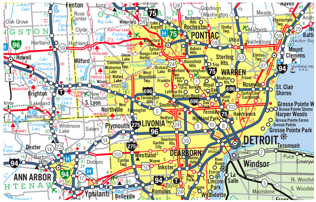
 Our Construction company is Servicing Southeast Michigan, Detroit and the Tri-County area Wyane, Oakland and Macomb;

